 NX-1000/NX-1500 NX-1000/NX-1500
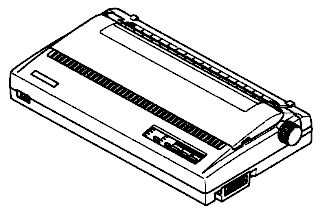
|
Language:
Epson FX, IBM Proprinter Speed: 150 cps (Draft pica)37.5 cps (NLQ pica) Memory: 15 KB1 line (max) Graphics: 60, 180, 360 DPI No. of Pins: 9 |


Internal Fonts
Typeface Quality Pitches Highlights
| Draft | Draft | ||
| Courier | NLQ | ||
| SanSerif | NLQ | ||
| Orator | NLQ |
Standard Feeders:
Friction and Push Tractor
Optional Feeders: Pull
Tractor
Continuous Feeding
Loading Fanfold Paper (Rear Feed)
1. Place a stack of fanfold paper behind and at least one page-length below the printer.
2. Turn the printer's power OFF.
3. Push the release lever to the upward position. This has the effect of releasing the paper from the platen roller, and engaging the tractor feed.
4. Remove the paper guide and put it aside for the moment.
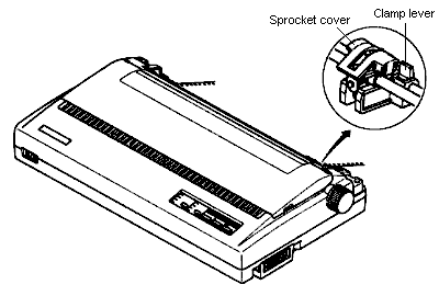
5. Remove the read cover. Grip it by its read edge and lift upwards and backwards.
6. With the sprocket covers open, thread the paper over the sprockets, aligning holes with the pins on the sprockets.
7. Adjust the spacing of the sprockets by sliding them along the bar, using the clamp lever at the back of each sprocket to release and lock the sprocket in position (when the lever is down, the sprocket may be moved, and when it is up, the sprocket is locked).
8. Now close the sprocket covers, again making sure that the paper sprocket holes are aligned with the pins on the sprockets. If they are not aligned properly, you will have problems with paper feeding, possibly resulting in tearing and jamming of the paper.
9. Turn on the printer using the switch at the front of the printer. The printer will beep (indicating that the paper is not yet fully loaded). This is also confirmed by the orange POWER indicator flashing.
10. Now press the [SET/EJECT/PARK] button. The paper bail will move clear of the paper, and the paper will be fed and adjusted past the print head to a position ready for printing. The paper bail will be moved back to grip the paper against the platen, and the print head will move to the start position.
11. Remount the rear cover. Hold it tilted upward and insert the four tabs at the front into their slots. Then rotated the cover downwards, pressing down on the thumb pads on the left and right to snap it into place.
12. Mount the paper guide in the horizontal position, so that it will separate the printed from the unprinted paper.
Loading Fanfold Paper (Bottom Feed, requires option Pull Tractor unit)
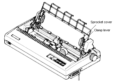
1. Remove the top cover, then move the bail lever on top of the printer forward to open the paper bail.
2. Mount the optional pull tractor unit onto the printer. Grip the lock levers on both sides and push the unit downwards onto the platen roller shaft to fit the tractor grips.
3. Place a stack of fanfold paper below the printer.
4. With the sprocket covers open, thread the paper over the sprockets from the bottom of the printer, aligning holes with the pins on the sprockets.
5. Adjust the spacing of the sprockets by sliding them along the bar, using the clamp lever at the back of each sprocket to release and lock the sprocket in position (when the lever is up, the sprocket may be moved, and when it is down , the sprocket is locked).
6. Now close the sprocket covers, again making sure that the paper sprocket holes are aligned with the pins on the sprockets. If they are not aligned properly, you will have problems with paper feeding, possibly resulting in tearing and jamming of the paper.
7. Mount the new top cover.
Manual Feeding
Loading Single Sheets While Printer is ON
1. Place the paper guide in position, locating the lugs on the bottom of the assembly into the slots on the rear cover of the printer.
2. Make sure that the release lever is down.
If the fanfold paper is mounted on the printer, press the [SET/EJECT/PARK] button to park the paper, then move the release lever downwards.
3. Adjust the paper guides to match the size of paper you will be using (remembering that printing will start some distance from the left-hand edge of the carriage).
4. Place a single sheet between the guides, placing the side on which you want to print towards the back of the printer. Gently push the paper down in the guides until you feel it stop.
5. Turn on the power using the switch at the front of the printer. The printer will beep, indicating that no paper is in position for printing. The orange POWER indicator also flashes to show this.
6. Now press the [SET/EJECT/PARK] button. The paper bail will move clear of the paper, and the paper will be fed and adjusted past the print head to a position ready for printing. The paper bail will be moved back to grip the paper again the platen, and the print head will move to the start position.
Loading Single Sheets While Printer is OFF
1. Place the paper guide in position, locating the lugs on the bottom of the assembly into the slots on the rear cover of the printer.
2. Check that printer power is off and the release lever at the back of the printer is down.
3. Open the top cover , then move the bail lever on top of the printer forward to open the paper bail.
4. Adjust the paper guides to match the size of paper you will be using (remembering that printing will start some distance from the left-hand edge of the carriage).
5. Place a single sheet between the guides, placing the side on which you want to print towards the back of the printer. Gently push the paper down in the guides until you feel it stop.
6. Turn the platen knob clockwise until the front edge of the paper comes out from under the top cover.
7. If the paper is not straight, move the release lever to the up position, straighten the paper by hand, then move the release lever back down.
8. Move the bail lever back to close the paper bail.
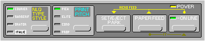
Short Self Test Turn on the printer with the [ONLINE] button pressed.
Long Self Test Turn on the printer with the [PAPER FEED] button pressed.
Location of DIP Switches
When you remove the
printer's cover and look inside, you will see on the green board
at the bottom of the printer two groups of small white switches
marked DSW1 and DSW2. These are the printer's DIP switches. DSW1
has eight switches, names 1-1 to 1-8 from left to right. DSW2 has
eight switches named 2-1 to 2-8.
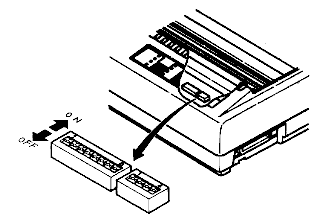
For all switches, the ON position is towards the back of the printer and the OFF position is towards the front. To set a DIP switch, use a ball-point pen or other small implement to move the switch to the ON or OFF position.
The printer's power should be off when you set the DIP switches. Settings made while power is on do not take effect until power is switched off, then on again, because the printer reads the DIP switches only at power-up.
DIP Switch Settings
DSW1
Page Length 11 inches ![]()
![]()
![]()
![]()
![]()
![]()
![]()
![]()
![]()
12 inches ![]()
![]()
![]()
![]()
![]()
![]()
![]()
![]()
![]()
Auto Carriage Return (CR)
Yes ![]()
![]()
![]()
![]()
![]()
![]()
![]()
![]()
![]()
No ![]()
![]()
![]()
![]()
![]()
![]()
![]()
![]()
![]()
Bottom Margin None ![]()
![]()
![]()
![]()
![]()
![]()
![]()
![]()
![]()
1 inch ![]()
![]()
![]()
![]()
![]()
![]()
![]()
![]()
![]()
Auto sheet feeder Inactive ![]()
![]()
![]()
![]()
![]()
![]()
![]()
![]()
![]()
Active ![]()
![]()
![]()
![]()
![]()
![]()
![]()
![]()
![]()
Paper-out detector Enabled ![]()
![]()
![]()
![]()
![]()
![]()
![]()
![]()
![]()
Disabled ![]()
![]()
![]()
![]()
![]()
![]()
![]()
![]()
![]()
Printer mode Standard ![]()
![]()
![]()
![]()
![]()
![]()
![]()
![]()
![]()
IBM ![]()
![]()
![]()
![]()
![]()
![]()
![]()
![]()
![]()
Char. Set (Standard mode)
Italics ![]()
![]()
![]()
![]()
![]()
![]()
![]()
![]()
![]()
Graphics ![]()
![]()
![]()
![]()
![]()
![]()
![]()
![]()
![]()
Char. Set (IBM mode) Set #2 ![]()
![]()
![]()
![]()
![]()
![]()
![]()
![]()
![]()
Set #1 ![]()
![]()
![]()
![]()
![]()
![]()
![]()
![]()
![]()
Auto Linefeed (LF) No ![]()
![]()
![]()
![]()
![]()
![]()
![]()
![]()
![]()
Yes ![]()
![]()
![]()
![]()
![]()
![]()
![]()
![]()
![]()
DSW2
Usage of RAM Buffer ![]()
![]()
![]()
![]()
![]()
![]()
![]()
![]()
![]()
Download ![]()
![]()
![]()
![]()
![]()
![]()
![]()
![]()
![]()
International character set
U.S.A. ![]()
![]()
![]()
![]()
![]()
![]()
![]()
![]()
![]()
France ![]()
![]()
![]()
![]()
![]()
![]()
![]()
![]()
![]()
Germany ![]()
![]()
![]()
![]()
![]()
![]()
![]()
![]()
![]()
England ![]()
![]()
![]()
![]()
![]()
![]()
![]()
![]()
![]()
Denmark I* ![]()
![]()
![]()
![]()
![]()
![]()
![]()
![]()
![]()
Sweden ![]()
![]()
![]()
![]()
![]()
![]()
![]()
![]()
![]()
Italy ![]()
![]()
![]()
![]()
![]()
![]()
![]()
![]()
![]()
Spain I ![]()
![]()
![]()
![]()
![]()
![]()
![]()
![]()
![]()
* Denmark/Norway when switch DSW1-6 is OFF and switch DSW1-7 is ON.
Font Style and Pitch Courier
10 CPI ![]()
![]()
![]()
![]()
![]()
![]()
![]()
![]()
![]()
Prestige 12 CPI ![]()
![]()
![]()
![]()
![]()
![]()
![]()
![]()
![]()
Orator 10 CPI ![]()
![]()
![]()
![]()
![]()
![]()
![]()
![]()
![]()
Script 12 CPI ![]()
![]()
![]()
![]()
![]()
![]()
![]()
![]()
![]()
Option 10 CPI ![]()
![]()
![]()
![]()
![]()
![]()
![]()
![]()
![]()
Draft 17 CPI ![]()
![]()
![]()
![]()
![]()
![]()
![]()
![]()
![]()
Draft 12 CPI ![]()
![]()
![]()
![]()
![]()
![]()
![]()
![]()
![]()
Draft 10 CPI ![]()
![]()
![]()
![]()
![]()
![]()
![]()
![]()
![]()
Printing Area A type** ![]()
![]()
![]()
![]()
![]()
![]()
![]()
![]()
![]()
B type** ![]()
![]()
![]()
![]()
![]()
![]()
![]()
![]()
![]()
** This printer can use two types of printing area format for single sheets. By putting the switch ON ("A type"), the top of the first line of print will start one inch from the top of the paper, and the printed area will end 6 mm from the bottom of the paper. By putting the switch OFF ("B type"), the top of the first line of print will start 1/6 inch from the top of the paper, and the printed area will end 1/3 inch from the bottom of the paper.
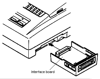
The interface connector is
located on the right side of the printer towards the front.
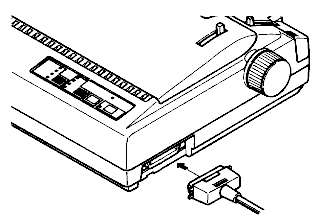
Parallel
Availability: Standard
Connection: Centronics (Amphenol 36 pin female)
Activation: Default
Serial
Availability:
Optional
Connection: DB25 female